Machining Thin Wall Aluminum Enclosures for Satellites — Tolerances, Fixturing and What Most Shops Get Wrong
Machining Thin Wall Aluminum Enclosures for Satellites — Tolerances, Fixturing and What Most Shops Get Wrong
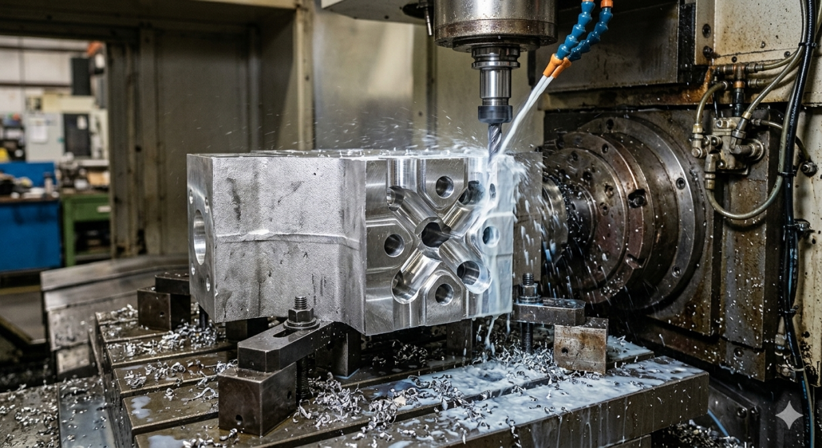
There is a particular kind of silence in the shop when you are running a 0.6mm wall on a satellite panel.
No conversation. No distraction. Just the sound of the spindle, the feed, and the instinct built from years of reading how aluminum behaves when there is almost nothing left of it.
Satellite enclosures — the housings that protect avionics, RF systems, and power electronics aboard small satellites and spacecraft — are among the most demanding components a CNC shop can produce. They are lightweight by necessity, structurally critical by function, and dimensionally unforgiving by design. A wall that springs 0.05mm out of tolerance does not get a concession. It gets scrapped.
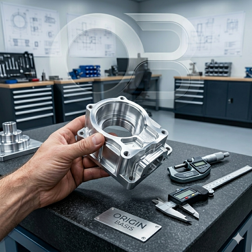
At ORIGINBASIS, we machine these components from 7075-T6 aluminum for space and defense programs. This post is a technical account of what that work actually involves — the material behavior, the fixturing philosophy, the cutting strategy — and the mistakes we see repeatedly when enclosures come to us after another shop could not hold the tolerance.
Why 7075-T6 and Why It Is Harder Than It Looks
When an aerospace engineer specifies 7075-T6 for a satellite enclosure, they are making a deliberate choice. The alloy offers a tensile strength approaching 570 MPa with a density of only 2.81 g/cm³ — one of the best strength-to-weight ratios available in aluminum. For a structure that must survive launch loads, thermal cycling between -180°C and +150°C, and the vibration environment of a rocket fairing, 7075-T6 makes engineering sense.
What it does not make is easy machining.
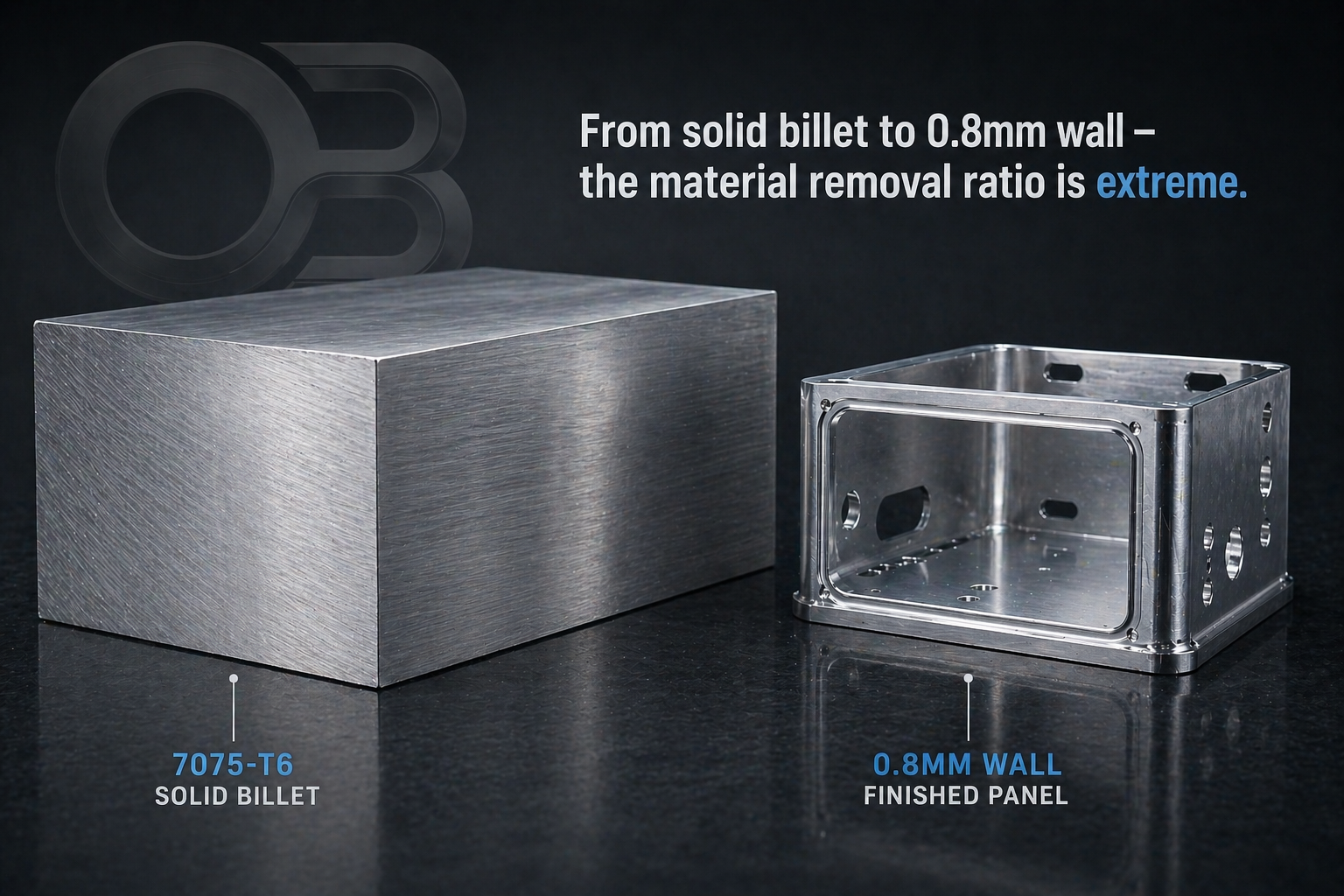
7075 is more prone to work hardening than 6061. It is stickier at the cutting edge in thin section. And critically, the residual stresses locked into the billet during the T6 aging process do not announce themselves until you have removed enough material that the part no longer has the rigidity to resist them. A 40mm thick billet can look perfectly stable through roughing. Remove material down to a 0.8mm wall and that same part will bow, spring, or twist as stress redistributes — sometimes visibly, sometimes by just enough to push a flatness callout out of tolerance.
This is not a machining problem. It is a materials physics problem, and most shops do not account for it until they see the first scrap part.
What Thin Wall Actually Means in This Context
When we say thin wall for satellite enclosures, we mean walls in the range of 0.5mm to 1mm. At 0.8mm, you are working with an aluminum section roughly as thick as a credit card. At 0.5mm, you are closer to heavy-gauge foil.
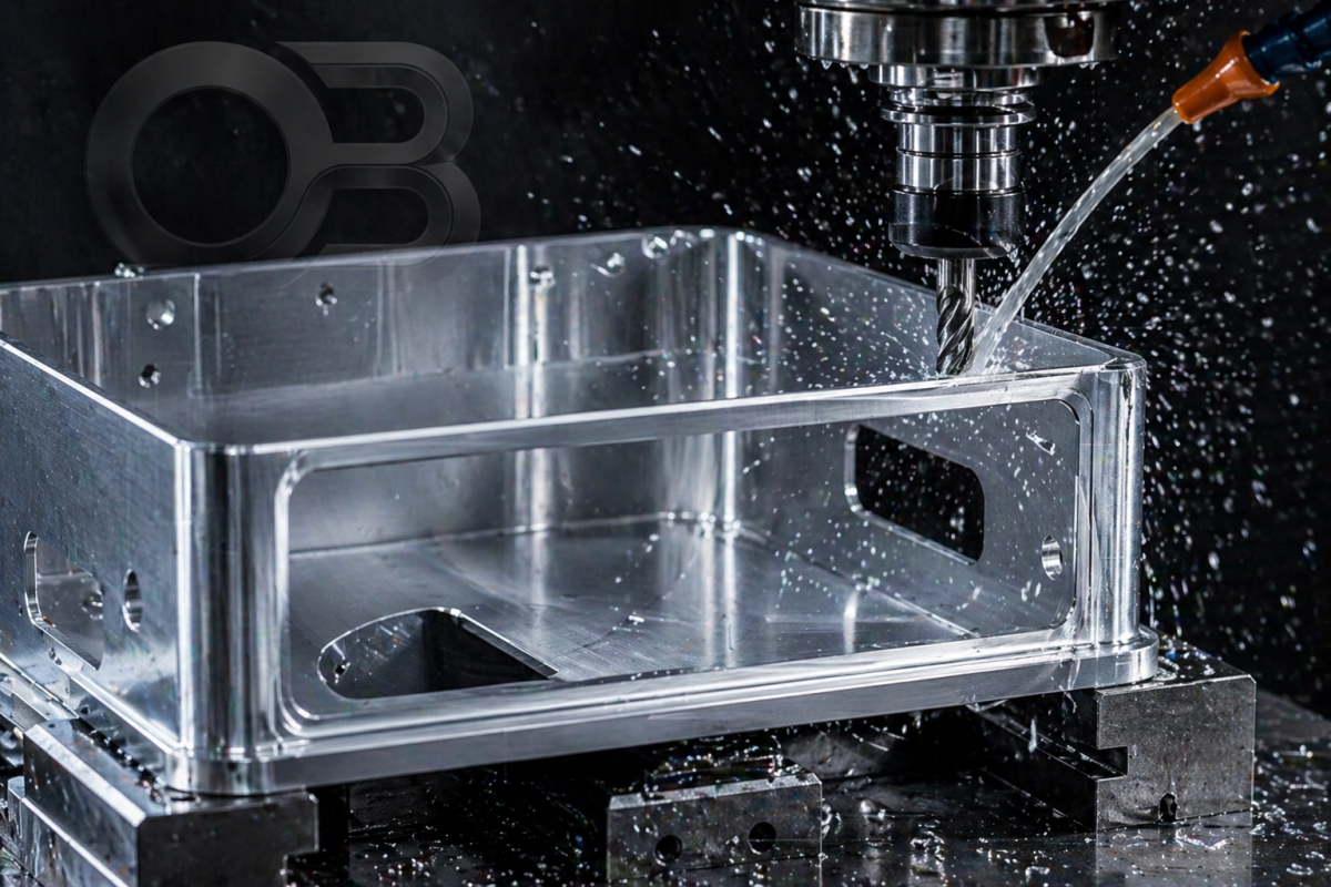
At these thicknesses, the wall itself becomes the compliance in the system. It deflects under cutting forces. It vibrates at frequencies that align with your spindle harmonics. It transmits heat from the cutting zone in ways that thicker sections never would. And it has essentially no margin for rework — if you take material off to clean up a surface and go 0.05mm deep, you may have just moved the wall below minimum.
The tolerance bands on these features are typically ±0.05mm on wall thickness and flatness callouts of 0.1mm or better across panels that may be 300mm to 500mm in their longest dimension. Achieving this consistently, across a batch, is the actual challenge.
Fixturing: The Decision That Determines Everything
If there is one thing that separates shops that can machine these parts from shops that cannot, it is fixturing philosophy.
Most job shops approach workholding the way they approach any aluminum part — clamp it down, hold it rigid, machine it. For thin wall aerospace enclosures, this approach produces scrap.
The problem is overclamping. When you apply heavy clamping force to a thin-walled structure, you elastically deform it. The part conforms to your fixture surface under clamping load. You machine it in that deformed state. When you release the clamps, the part springs back — and your precisely machined walls are now out of flat.
The correct approach is what we call compliant fixturing: using the minimum clamping force necessary to prevent workpiece movement under cutting loads, distributing that force across as many contact points as possible, and supporting the part from below so that unsupported spans are as short as possible.
For satellite panels specifically, this often means machining custom soft-jaw sets for each part number, and designing the fixturing sequence so that the last operation leaves the critical datum surfaces completely unloaded when tolerances are checked.
We also stage the machining sequence deliberately — roughing with generous stock, then a stress relief step where the part is allowed to move freely before semi-finishing, then a final skim pass at minimum depth and feed to achieve tolerance. This three-stage approach adds time. It also adds reliability that a single-setup approach cannot match.
Cutting Strategy for 0.5mm–1mm Walls
Once fixturing is handled correctly, the cutting strategy for thin walls follows a set of clear principles.
Radial depth of cut is your primary control. In thin wall machining, axial depth can remain relatively high while radial engagement must be kept very low — typically 5% to 10% of tool diameter. This minimises the radial cutting force that causes wall deflection while allowing reasonable material removal rates.
Climb milling only. Conventional milling generates cutting forces that push the wall away from the tool, then pull it back as the engagement reverses. At thin wall thicknesses, this creates chatter that cannot be damped. Climb milling keeps the force direction consistent and predictable.
Toolpath direction relative to the wall matters. We machine parallel to the wall in the finishing passes — not perpendicular to it. Perpendicular passes create a bending moment on the unsupported wall section. Parallel passes create a compressive load that the wall can resist.
High spindle speed, high feed, shallow cut. For 7075-T6 at 0.8mm wall, we run significantly higher surface speeds than we would for structural aluminum work — keeping the chip thin, the engagement brief, and the heat in the chip rather than in the part. Dwelling on a surface at slow feed is how you work-harden 7075 and destroy your tool life simultaneously.
Coolant strategy is not optional. We use high-pressure through-spindle coolant for all finishing passes on thin wall sections. The goal is chip evacuation as much as temperature control — a recutting chip dragged across a 0.6mm wall is a fast path to a surface that does not inspect.
What Most Shops Get Wrong
In our experience taking on work that other shops have struggled with, the failure modes are remarkably consistent.
They use the wrong tool geometry. General-purpose end mills designed for structural aluminum have too much radial rake and too little axial relief for thin wall work. The cutting forces are simply too high. Correct tooling for this application uses geometry optimised for low cutting forces, not maximum material removal rate.
They do not account for part spring. The standard approach of measuring a wall at the machined surface while the part is still in the fixture tells you nothing about what the wall will measure when the part is free. We always measure critical walls after unclamping and with the part supported only at its datum.
They try to hold tolerance in one setup. A single-setup approach works for structural components. For thin wall enclosures, the stress redistribution that happens as material is removed makes single-setup tolerance holding unreliable. The part needs an opportunity to move between roughing and finishing.
They use coolant incorrectly. Flood coolant applied intermittently causes thermal shock cycling in thin sections. Either run continuous, consistent coolant or run dry with air blast. Intermittent flood on hot aluminum causes micro-distortion that shows up in your flatness measurements.
They do not qualify the billet. 7075-T6 plate has internal stress variation across its cross-section. Billets cut from near the surface of the original plate behave differently from billets cut from the centre. For high-precision aerospace work, we qualify incoming material and, where possible, specify material that has been stress-relieved beyond the standard T6 process.
Why This Matters for Indian Space and Defense Programs
The challenge these industries face is the same challenge their global counterparts faced a decade ago: the precision machining supply chain has not kept pace with the design capability. There are many shops in Delhi NCR and the broader NCR region that can produce structural aluminum parts. There are very few that can hold ±0.05mm wall tolerances on 0.6mm sections in 7075-T6, with documentation that satisfies an aerospace quality audit.
That gap is where ORIGINBASIS operates.
We machine thin wall aerospace enclosures, structural panels, and housings for programs where dimensional tolerance is non-negotiable and where the documentation trail — material certs, in-process inspection records, first article reports — must be complete and traceable.
If you are sourcing precision aluminum enclosures for a satellite, UAV, or defense electronics program and your current supplier is struggling with flatness, wall thickness consistency, or yield, we are worth a conversation.
A Note on Documentation
One final point that procurement teams at aerospace and defense programs should be aware of: machining capability and documentation capability are not the same thing.
A shop can have excellent machining skills and still fail a supplier audit because their inspection records are incomplete, their material traceability is broken, or they cannot produce a first article inspection report that maps every critical dimension to a drawing callout.
At ORIGINBASIS, we produce full dimensional reports on first article submissions, maintain material certifications linked to specific job travellers, and document our process parameters for critical features so that results are repeatable across production runs — not just on the first part.
For space and defense programs, this is not optional. It is the baseline.
ORIGINBASIS is a precision CNC contract manufacturer based in Greater Noida, NCR, specialising in aerospace, defense, medical device, and high-technology components. We machine to aerospace standards and document to match.
Enquiries: Quote@originbasis.com | originbasis.com