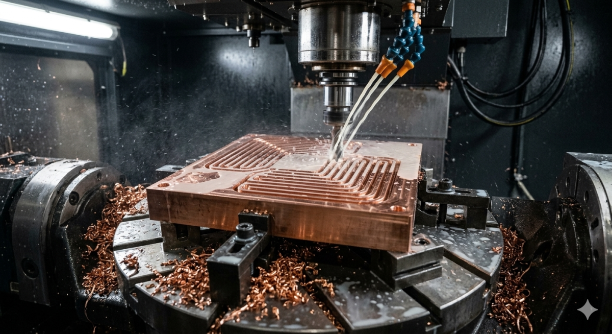
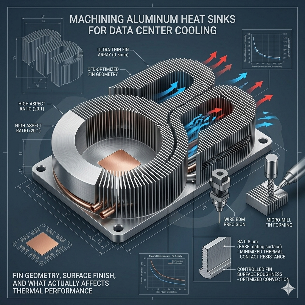
CNC Machining Considerations for 6061 Aluminum Liquid-Cooling Manifolds
As server racks in modern data centers reach unprecedented power densities, traditional air cooling is no longer sufficient. High-performance computing requires direct-to-chip liquid cooling, and at the heart of these thermal management systems are cold plates and cooling manifolds.
Manufacturing these manifolds is a high-stakes process. A single micro-scratch on an O-ring sealing surface or a slight deviation in channel flatness can result in catastrophic coolant leaks inside a server chassis.
This article reviews important CNC machining considerations for 6061 aluminum liquid-cooling manifolds. Origin Basis is establishing its Greater Noida facility for a planned April 2027 production opening. The discussion below describes manufacturing principles, not verified current Origin Basis production performance.
Why 6061 Aluminum?
For data center heat sinks and manifolds, 6061 aluminum is often the material of choice. It offers an optimal balance of thermal conductivity, structural integrity, and excellent machinability. While other alloys like 7075 offer higher yield strength, 6061 provides superior corrosion resistance—a critical factor when the component will be exposed to liquid coolants (like glycol-water mixtures) over a multi-year lifespan.
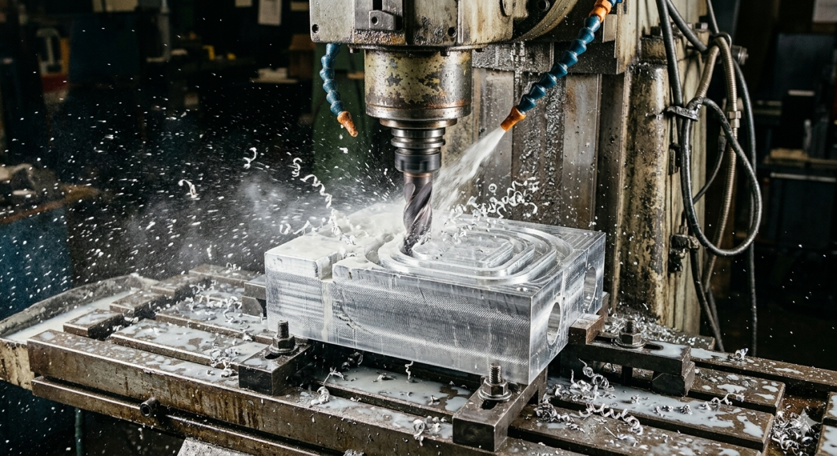
However, 6061's slight "gummier" nature compared to harder alloys means that aggressive chip evacuation and optimal tool paths are required to prevent built-up edge (BUE) on the cutting tools, which can quickly ruin a critical surface finish.
The Challenge: Sealing Surfaces and Part-Specific Tolerances
The internal geometry of a cooling manifold consists of complex fluid channels, inlet/outlet ports, and tight-tolerance O-ring grooves.
Sealing performance depends on the approved groove geometry, mating-surface condition, flatness, waviness, gasket or O-ring selection, assembly method, and operating conditions. A surface finish such as Ra 0.8 µm or a dimensional tolerance such as ±0.02 mm may apply to certain features, but neither value is universal. The drawing and sealing validation must define the actual acceptance criteria.
Manufacturing Strategy for Reliable Manifolds
1. Stress-Relieved Material and Rigid Setup
Material condition and residual stress should be considered before machining. Deep pockets and channels remove substantial material and may release internal stress. A process plan may use suitable stock condition, balanced material removal, controlled clamping, intermediate relaxation, or re-fixturing before finishing, depending on the component and flatness requirements.
2. Roughing and Chip-Evacuation Planning
Roughing strategy should balance material-removal rate, tool load, chip evacuation, heat input, and distortion risk. Tool type, coolant delivery, cutting direction, parameters, and engagement should be selected for the actual machine, geometry, material condition, and tooling. Effective chip evacuation helps reduce chip recutting and surface damage.
3. Precision Finishing Passes
Sealing grooves and mating faces generally require controlled finishing operations. Tool condition, runout, programmed path, entry and exit strategy, workholding stability, and inspection method should be defined according to the drawing and sealing requirements.
- O-ring Grooves: Review groove dimensions, corner radii, surface requirements, tool-entry locations, burr control, and inspection access. Continuous paths and suitable lead-in or lead-out moves may help avoid dwell marks where geometry allows.
- Mating Surfaces: Select a finishing strategy that can control the specified flatness and surface condition. Cutter size and toolpath alone do not guarantee a seal; machine condition, fixturing, material stability, inspection, assembly, and validation also matter.
4. Part-Specific Inspection
Inspection should match the component’s risks and drawing requirements. Depending on the part, this may include calibrated dimensional instruments, CMM inspection, surface-roughness measurement, thread verification, flatness assessment, cleanliness checks, and documented inspection results. Measurement capability must be suitable for the tolerance being reported.
5. Deburring and Leak-Validation Planning
Internal edges and channel intersections should be reviewed for burr-removal access and cleanliness requirements. If leak or pressure testing is required, the specification should define the medium, pressure, duration, allowable leakage, temperature, safety controls, documentation, and whether testing is performed internally or by an approved external provider.
What Buyers Should Verify
For liquid-cooling manifold sourcing, buyers should verify drawing review, material condition, sealing-feature control, burr removal, cleanliness, inspection capability, outside processes, leak-testing responsibility, traceability, and process-validation evidence. No machining supplier should promise leak-free service life without the applicable design, assembly, operating, and validation requirements.
Developing a liquid-cooling manifold or thermal-management component? Submit an advance enquiry to Origin Basis. Feasibility, equipment suitability, tolerance capability, inspection scope, testing responsibility, capacity, and timing will be confirmed after technical review and facility commissioning.