GD&T Datum Strategy in CNC Machining: How a Part Can Pass Dimensions and Still Fail Assembly
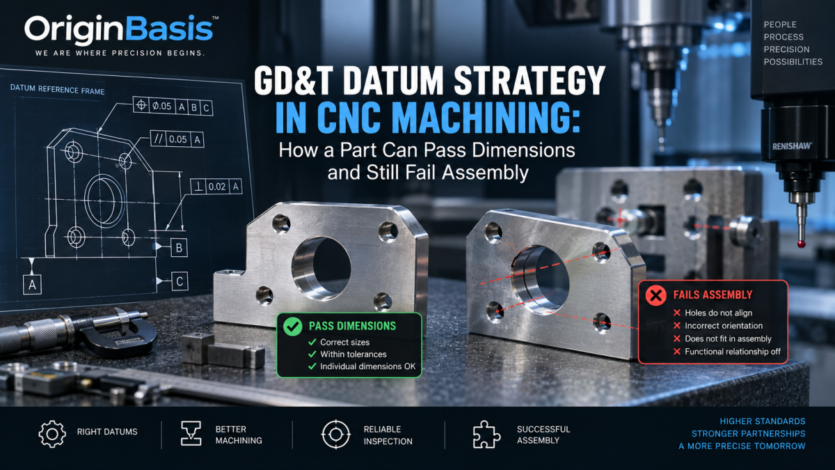
GD&T Datum Strategy in CNC Machining: How a Part Can Pass Dimensions and Still Fail Assembly
A CNC-machined component can be perfectly within its individual dimensional tolerances and still refuse to assemble correctly.
The hole diameters may be correct.
The overall length may be correct.
The thickness may be correct.
The hole-to-edge dimensions may even appear correct.
Yet when the component reaches the customer's assembly line, the bolts do not align, mating surfaces do not seat properly, or the part sits at an unexpected angle.
The problem may not be machining accuracy at all.
It may be the datum strategy.
For precision manufacturing, especially in aerospace, medical, automotive and other tightly controlled applications, GD&T is not simply a drawing language used by inspectors. It defines how a component is functionally located, oriented, manufactured and verified.
Understanding the relationship between datums, manufacturing setup and inspection is therefore essential to producing parts that work—not merely parts that measure correctly.
What Is a Datum in GD&T?
A datum is a theoretically exact reference used to establish the location or orientation of features on a component.
A physical surface, hole, pin or other feature identified on the drawing becomes a datum feature. During inspection or assembly, that feature is used to establish the theoretical datum.
A typical datum reference frame uses three levels of constraint:
Primary datum – A
Establishes the main reference plane and removes the first degrees of freedom.
Secondary datum – B
Orients the component relative to the primary datum and removes additional movement.
Tertiary datum – C
Completes the location of the component.
Together, A-B-C establish the coordinate system from which controlled features are evaluated.
This sounds straightforward, but the choice of those datums can determine whether the manufactured component functions correctly.
Dimensions Alone Do Not Describe Function
Consider a simple machined mounting plate.
The drawing contains four mounting holes.
Each hole may have:
- the correct diameter,
- acceptable X and Y coordinates,
- correct plate thickness,
- correct outside dimensions.
A conventional inspection could therefore conclude that the component is acceptable.
But imagine that the mounting face is slightly warped or the hole pattern is tilted relative to the surface that actually contacts the customer's assembly.
Each dimension may individually remain within tolerance.
However, when the plate is bolted onto the mating component, the mounting holes may no longer align correctly.
The dimensional values were acceptable.
The geometric relationship between the features was not.
That is exactly the problem GD&T is designed to control.
Datum Strategy Should Follow Part Function
One of the most important principles in GD&T is simple:
Datums should generally represent how the component functions in its real assembly.
Suppose a housing is installed against a large machined mounting face, positioned by one precision bore and clocked by another feature.
A logical functional datum structure may therefore be:
Datum A: mounting face
Datum B: locating bore
Datum C: clocking feature
Inspection using these references recreates, as closely as practical, how the part will actually be constrained during assembly.
Now imagine inspection instead references an easy-to-measure external surface that has no functional relationship with the mating assembly.
The inspection report may show excellent results.
But those results may not accurately represent the condition experienced when the customer installs the component.
That difference is critical.
The Difference Between a Manufacturing Datum and a Functional Datum
Manufacturing engineers naturally want convenient setup surfaces.
A machinist may prefer to locate a workpiece from a large, accessible face because it provides:
- stable workholding,
- simple probing,
- easy vise or fixture location,
- repeatable setups.
There is nothing inherently wrong with that.
But the manufacturing reference does not always have to be the same feature as the drawing's functional datum.
The important requirement is that the manufacturing process maintains the specified geometric relationship back to the drawing datums.
This distinction becomes especially important when a component requires multiple machining operations.
For example:
Operation 10
Machine the base surface.
Operation 20
Locate from the newly machined surface and produce critical bores.
Operation 30
Rotate the component and machine another feature.
Every time the part is relocated, additional variation can enter the process.
Without a well-planned datum-transfer strategy, small setup errors can accumulate until the final feature no longer maintains the required relationship to the functional datum reference frame.
Datum Transfer Between CNC Operations
Multi-operation machining requires careful planning.
Imagine a component containing:
- a precision mounting surface,
- two bearing bores,
- several bolt holes,
- a side port,
- a sealing surface.
It may require three or four CNC setups.
If each setup uses unrelated reference points, the component can slowly lose its relationship to the original functional datums.
A better process strategy is normally to create strong reference features early and preserve their relationship throughout later operations.
For example:
Operation 10: establish Datum A.
Operation 20: locate from Datum A and establish Datum B.
Operation 30: fixture from A and B while machining features controlled to those datums.
This creates a more traceable relationship between the drawing requirements and the manufacturing process.
The exact strategy depends on the component, tolerances, material, machine capability and workholding method.
Position Tolerance Demonstrates Why Datums Matter
Hole location is one of the easiest ways to understand this concept.
A drawing might specify:
Position Ø0.10 | A | B | C
This does not simply mean:
"The hole center must be within 0.10 mm of its nominal coordinates."
The tolerance controls the hole relative to a datum reference frame established by A, B and C.
Therefore, the result depends on how the component is oriented and located from those datums.
If inspection establishes the part from different surfaces than the drawing requires, the measured position result may be misleading.
The same principle applies to controls such as:
- perpendicularity,
- parallelism,
- profile,
- runout,
- orientation,
- location.
GD&T controls relationships—not merely individual dimensions.
A Common CNC Machining Failure
Consider an aluminum housing with a precision bearing bore.
The bore itself is measured and found to be:
Diameter: within tolerance
An inspector therefore assumes the feature is acceptable.
However, the bore axis is slightly tilted relative to the housing's mounting surface.
When the mating shaft is installed, alignment is poor.
The bore diameter was correct.
But the bore's orientation relative to the functional datum was incorrect.
Depending on the design, the engineering drawing might control this condition using position, perpendicularity, runout or another appropriate geometric control.
This is why checking size alone cannot confirm function.
Why Coordinate Measuring Machines Do Not Automatically Solve the Problem
A CMM can measure complex geometry with extraordinary precision.
But the accuracy of the equipment does not compensate for an incorrect measurement strategy.
Before evaluating a feature, the inspection method must correctly establish the required datum reference frame.
If the alignment is built from the wrong features, the CMM can produce extremely precise measurements relative to the wrong coordinate system.
This is an important distinction:
Measurement precision and measurement validity are not the same thing.
A sophisticated inspection report is useful only when the measurement method correctly represents the drawing requirement.
Datum Simulation Matters
Physical parts are imperfect.
A surface identified as Datum A is not a mathematically perfect plane. It contains some amount of:
- flatness variation,
- surface texture,
- machining marks,
- waviness.
During real assembly, the mating component contacts the high points of that surface.
Inspection therefore has to simulate the theoretical datum appropriately.
Depending on the feature and specification, datum simulation may involve:
- surface plates,
- fixture plates,
- pins,
- expanding mandrels,
- CMM alignment,
- dedicated checking fixtures.
This is another reason why datum selection affects far more than drawing interpretation.
It can influence manufacturing fixtures, inspection fixtures and even production cost.
Poor Datum Strategy Can Increase Manufacturing Cost
An unnecessarily complicated datum scheme can create problems even when technically achievable.
It may require:
- additional CNC setups,
- complex fixtures,
- tighter-than-needed process control,
- additional probing,
- expensive inspection fixtures,
- increased CMM time,
- more frequent rework.
Good product design therefore considers both function and manufacturability.
The objective should not simply be to apply tight tolerances.
The objective should be to control the features that matter to product function while allowing reasonable manufacturing variation elsewhere.
CNC Process Planning Should Begin With the Datum Structure
Before programming a precision component, the manufacturing team should understand the drawing's datum reference frame.
A useful planning discussion includes:
- Which surfaces actually locate the component during assembly?
- Which feature establishes the primary datum?
- Which features establish secondary and tertiary location?
- Which characteristics are controlled from those datums?
- Which datums should be established during the first machining operations?
- How will those datums be transferred between setups?
- How will the finished features be inspected?
- Can the inspection method reproduce the functional datum reference frame?
Answering these questions before machining can prevent significant problems later.
Fixture Design and Datum Strategy Are Closely Connected
Good workholding is not merely about preventing a component from moving.
A fixture should locate the workpiece in a repeatable way while supporting the manufacturing requirements of the drawing.
The familiar 3-2-1 locating principle illustrates this concept.
A workpiece can be constrained using:
- three points on the primary locating plane,
- two points on the secondary plane,
- one point on the tertiary plane.
The principle closely resembles how a datum reference frame progressively constrains a component.
For precision parts, fixture designers should also consider distortion from clamping.
A perfectly designed datum strategy can still fail if excessive clamping force bends a thin-wall component during machining.
After the component is released, it may move outside its required geometric condition.
The Assembly Is the Final Test
Manufacturing drawings exist to communicate design intent.
Inspection exists to verify that intent.
But ultimately, the component has to function in the real product.
This is why a technically impressive dimensional report cannot replace an understanding of assembly requirements.
A supplier should not only ask:
"Can we hold this dimension?"
The better questions are:
"What is this feature locating?"
"What does it mate with?"
"Which datum controls its function?"
"How will we preserve that relationship through every machining setup?"
"How will we verify it during inspection?"
Those questions move manufacturing from dimension checking toward process control and functional quality.
Datum Strategy Becomes More Important as Tolerances Tighten
When tolerances are relatively open, small differences between setups may have little effect.
As tolerances become tighter, datum strategy becomes increasingly important.
This is particularly relevant for components involving:
- precision bores,
- bearing locations,
- sealing surfaces,
- aerospace structures,
- medical-device components,
- hydraulic manifolds,
- optical components,
- thin-wall housings,
- robotic assemblies,
- precision fixtures.
At this level, dimensional accuracy alone is not sufficient.
The manufacturer has to control the relationship between features throughout the entire manufacturing process.
From Drawing to Manufacturing Process
A mature precision-machining process connects four things:
Design intent → Datum structure → CNC process → Inspection strategy
They should not operate independently.
The engineering drawing defines how the component is expected to function.
Process engineering determines how those relationships will be created.
CNC machining establishes the geometry.
Inspection verifies that the manufactured component remains within the required datum reference frame.
When all four are aligned, manufacturing becomes considerably more predictable.
When they are disconnected, a component can reach final inspection with an impressive dimensional report and still fail when the customer tries to assemble it.
Conclusion
One of the most important lessons in precision machining is that a part is more than a collection of dimensions.
The relationship between its surfaces, holes, bores, axes and mating features often determines whether the component actually works.
That is why datum strategy should be considered before machining begins—not discovered after an assembly problem occurs.
A strong CNC manufacturing process does not simply ask whether every dimension is within tolerance.
It ensures that the part has been:
located correctly, machined correctly, related to the correct functional datums and inspected using the same design intent.
Because ultimately, the goal is not to manufacture a part that passes an inspection report.
The goal is to manufacture a part that works correctly when it reaches the customer's assembly.
OriginBasis
At OriginBasis, our approach to precision manufacturing is built around understanding the relationship between drawing requirements, manufacturing processes, inspection and final part function.
We are where precision begins.