CNC Process Capability: Why One Good First Article Does Not Prove Your Supplier Can Produce 500 Good Parts
CNC Process Capability: Why One Good First Article Does Not Prove Your Supplier Can Produce 500 Good Parts
A supplier machines the first component from your purchase order.
The dimensional report looks excellent.
Every critical feature is within tolerance. The surface finish is acceptable. The CMM report passes. The first article is approved.
So the supplier is ready to manufacture 500 parts, right?
Not necessarily.
A successful first article proves something important: the supplier was capable of producing that particular part, under those particular conditions, at that particular point in time.
It does not automatically prove that the underlying manufacturing process is stable enough to produce part number 1, part number 87, part number 263 and part number 500 to the same requirements.
That distinction matters enormously in aerospace and other high-reliability manufacturing environments.
For Supplier Quality Engineers, manufacturing engineers and procurement teams, supplier qualification should therefore go beyond asking:
"Can this supplier make the part?"
The more important production question is:
"Can this supplier control the process that makes the part?"
A First Article Is a Snapshot. Production Capability Is a System.
First Article Inspection is an important manufacturing verification step.
It can help confirm that the manufacturing planning, tooling, programming, setup and inspection approach are capable of producing a component that conforms to the engineering definition.
But a first article remains essentially a snapshot of the process.
Imagine a drawing requires a precision bore of:
Ø20.000 ±0.010 mm
Your supplier produces the first component at:
Ø20.001 mm
Excellent result.
But what happens as production continues?
Will part 100 measure 20.003 mm?
Will part 250 measure 20.008 mm?
Will part 400 measure 20.011 mm and become nonconforming?
The answer depends on much more than the accuracy of the first component.
It depends on the stability and control of the entire manufacturing process.
The Real Question: Where Will the Process Be After Hundreds of Parts?
CNC machining is highly repeatable, but it is not immune to variation.
Every manufacturing process contains sources of variation.
A capable supplier understands those sources and develops controls around them instead of assuming that because the CNC program has not changed, the process has not changed.
For a 500-piece production order, several variables deserve particular attention.
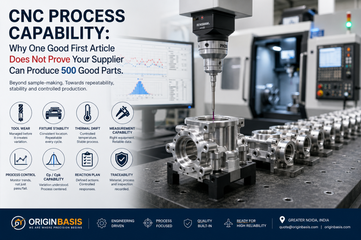
1. Tool Wear: The Cutter Making Part 1 Is Not the Same Cutter Making Part 300
Cutting tools wear.
That sounds obvious, but the effect of progressive tool wear on dimensional stability is one of the fundamental differences between making samples and controlling production.
As a cutting edge wears, several things can change:
- cutting forces;
- effective cutting diameter;
- heat generation;
- tool deflection;
- surface finish;
- burr formation;
- dimensional accuracy.
Consider an end mill finishing a precision wall.
The first 20 components may remain comfortably near nominal. As the tool wears, however, the dimension may progressively move toward one side of the tolerance.
A supplier relying only on final inspection could eventually discover the problem after nonconforming parts have already been produced.
A controlled production process takes a different approach.
Tool life may be monitored by number of components, cutting time, dimensional trend, surface condition or another defined method appropriate to the application.
For critical features, the objective is not simply to use the tool until it fails.
The objective is to recognize and manage predictable deterioration before product conformity is affected.
2. Fixture Stability: Repeatability Starts With How the Part Is Located
A sophisticated CNC machine cannot compensate for an unstable workholding strategy.
Fixtures influence:
- part location;
- datum repeatability;
- clamping distortion;
- accessibility;
- rigidity;
- vibration;
- repeat loading accuracy.
A first article may be produced with exceptional care.
The machinist cleans every locating surface, carefully loads the component, checks the setup and manually confirms critical dimensions.
Production is different.
The fixture must continue locating components consistently through repeated loading, unloading, chip exposure, coolant, clamping cycles and operator interaction.
For this reason, production fixture design must consider more than simply holding the component securely.
It should consider how consistently the component returns to its intended datum structure every cycle.
A process capable of making 500 conforming components therefore depends heavily on repeatable location and controlled clamping.
3. Thermal Drift: CNC Machines Do Not Operate in a Thermal Vacuum
Machine tools generate heat.
Spindles warm.
Ball screws warm.
Coolant temperature changes.
The surrounding shop environment changes.
The workpiece itself can heat during machining.
These thermal effects may be relatively insignificant for generous tolerances, but they become increasingly important as tolerances tighten.
Consider the difference between measuring the first component shortly after startup and measuring parts after several hours of continuous machining.
The program may be identical.
The cutting tools may appear acceptable.
Yet the thermal state of the machine can be different.
For tight-tolerance production, manufacturers need to understand questions such as:
- Does the machine require a defined warm-up routine?
- Are critical dimensions sensitive to spindle temperature?
- Is coolant temperature affecting the workpiece?
- Are offsets changing as the process reaches thermal equilibrium?
- Are parts being inspected at a consistent temperature?
- Does the process remain centered throughout the shift?
This is one reason serious precision machining is not simply about buying a machine with an impressive positioning specification.
The complete process must be understood.
4. Material Variation Can Change Machining Behaviour
The drawing may specify the same material for every component, but incoming material is not perfectly identical.
Different lots may exhibit differences in:
- hardness;
- residual stress;
- condition;
- microstructure;
- stock geometry;
- surface condition;
- material removal behaviour.
These differences can influence cutting forces, distortion, tool wear and final dimensions.
Thin-wall components are especially sensitive.
A component may measure correctly while restrained in the fixture but move after unclamping because machining has released internal stresses.
A process developed around one bar, plate or forging should therefore not automatically be assumed to behave identically across every material lot.
For critical production, material traceability and process knowledge work together.
5. Measurement Variation Matters Too
Another question is frequently overlooked:
Can the measurement system reliably distinguish process variation from measurement variation?
A machining process cannot be intelligently controlled if its measurement system is unreliable.
Depending on the feature and tolerance, inspection may involve:
- CMM;
- micrometers;
- bore gauges;
- height gauges;
- air gauging;
- surface roughness equipment;
- optical measurement;
- functional gauges.
The equipment must be appropriate for the characteristic being measured, and measurement methods need sufficient resolution and repeatability for the tolerance being controlled.
There is little value in attempting to control a very tight machining process using a measurement method that introduces significant uncertainty of its own.
This Is Where Process Capability Becomes Important
Producing one dimension inside its tolerance tells you whether that particular result conforms.
Process capability asks a different question:
How does the distribution of the manufacturing process behave relative to the engineering tolerance?
Two commonly discussed indices are Cp and Cpk.
Cp — Potential Process Capability
Cp compares the available specification width with the natural spread of the process.
In simplified form:
Cp = (USL − LSL) / 6σ
where:
- USL = Upper Specification Limit
- LSL = Lower Specification Limit
- σ = estimated process standard deviation
Cp tells us about process spread, but it assumes the process is appropriately centered.
And that is an important limitation.
Cpk Adds Something Critical: Process Centering
Cpk considers both process variation and where the process mean sits within the tolerance.
A process may have very little variation but still be operating dangerously close to one specification limit.
For example, imagine a dimension with relatively tight, consistent results.
That sounds good.
But if all those results are clustered near the upper tolerance limit, a relatively small amount of tool wear or thermal movement could begin producing nonconforming components.
This is why looking only at variation—or worse, looking at one perfect first article—is insufficient.
A capable production process should generally be both:
stable enough in variation and appropriately centered within the specification.
The specific statistical requirements should ultimately be defined by the customer, drawing, quality plan or applicable program requirements rather than assumed universally.
Process Stability Comes Before Capability Numbers
There is another important point.
A Cpk number should not become a marketing number disconnected from the manufacturing process.
Before capability statistics provide meaningful information, the underlying process should be understood and reasonably stable.
Suppose an operator continually adjusts offsets after every measurement.
The resulting dimensions might remain within tolerance.
But that does not necessarily represent a naturally stable process.
Instead, the operator may be actively compensating for an uncontrolled condition.
That may occasionally be necessary, but engineering teams should understand why intervention is required and whether the intervention itself is controlled.
The objective is not simply to calculate Cpk.
The objective is to establish a manufacturing process whose behaviour can be understood, monitored and controlled.
What Controlled CNC Production Should Look Like
For an aerospace or other precision component, moving from first article to repeat production should involve a structured approach.
1. Identify Critical Characteristics
Not every dimension needs the same level of control.
The manufacturing team should understand which characteristics are most important to:
- fit;
- function;
- assembly;
- safety;
- interchangeability;
- downstream processing.
Critical and tight-tolerance characteristics may require increased inspection frequency or statistical monitoring.
2. Establish a Repeatable Datum and Fixture Strategy
The fixture needs to reproduce the drawing datum structure as practically and consistently as possible.
Clamping methods should minimize distortion while providing the rigidity required for machining.
3. Control Tools and Tool Life
Tools influencing critical characteristics should not be treated as unlimited-life consumables.
Defined replacement criteria, inspection frequency or dimensional trend monitoring can help prevent progressive wear from generating defects.
4. Establish Machine and Thermal Controls
Where thermal behaviour can influence dimensions, the production plan should consider machine warm-up, coolant condition, machining sequence and measurement conditions.
5. Define Inspection Frequency
Inspecting the first component and then waiting until component 500 is not process control.
Inspection frequency should reflect the risk associated with the feature and the manufacturing process.
A control plan might require inspection of certain characteristics:
- at setup;
- after tool replacement;
- at defined production intervals;
- following an offset adjustment;
- after an interruption;
- at final inspection.
The exact strategy should be determined for the component rather than applied blindly.
6. Watch Trends, Not Just Pass/Fail Results
This is particularly important.
Imagine the upper specification limit is 10.050 mm.
Your measurements are:
10.011
10.015
10.020
10.027
10.033
10.039
10.044
Every part still passes.
But the trend is telling you something.
Waiting until the dimension reaches 10.051 mm before reacting means the process has already been giving warning signs.
A mature manufacturing system examines process behaviour, not merely whether today's measurement has a green check mark beside it.
7. Define a Reaction Plan
What happens if a measurement begins trending toward a limit?
A controlled production process should have a defined response.
Depending on the situation, that could include:
- stopping production;
- verifying measurement;
- checking tool condition;
- checking fixture location;
- replacing a tool;
- investigating thermal effects;
- correcting an offset through an authorized method;
- identifying potentially affected material;
- increasing inspection frequency.
The key principle is simple:
The response should be systematic rather than improvised.
What Aerospace SQEs and Procurement Teams Should Ask Their CNC Suppliers
Supplier evaluation should therefore go beyond requesting photographs of CNC machines and a passing dimensional report.
Useful questions include:
- How will you control the critical dimensions throughout the production lot?
- Which features are expected to move as tools wear?
- How is tool life established and monitored?
- How does your fixture ensure repeatable datum location?
- How do you address part distortion after unclamping?
- What machine warm-up or thermal-control methods are used for tight tolerances?
- What inspection equipment will be used for each critical characteristic?
- What inspection frequency will be used during production?
- Will dimensional trends be monitored rather than only pass/fail results?
- What happens when a process begins approaching a specification limit?
- How are tool changes, offset adjustments and process changes documented?
- How will material, inspection and production records remain traceable to the manufacturing lot?
The answers tell you considerably more about a supplier's manufacturing maturity than a single perfect sample.
Prototype Machining and Production Machining Require Different Thinking
Producing a prototype requires skill.
Producing hundreds of interchangeable components requires skill plus process discipline.
A talented machinist can often nurse a difficult component through manufacturing by:
- repeatedly checking dimensions;
- manually adjusting offsets;
- changing machining sequence;
- selecting individual tools;
- making small corrections.
That approach can be entirely appropriate during development.
But production cannot depend indefinitely on one person's intuition.
Knowledge has to move from the machinist's head into the manufacturing process.
That means documented setups, controlled tooling, defined inspection, repeatable workholding, appropriate measurement, traceability and reaction plans.
This transition—from making a good part to building a capable process—is one of the most important stages in precision manufacturing.
The ORIGINBASIS Approach: Build the Process, Not Just the Sample
At ORIGINBASIS, this distinction is central to the manufacturing system being developed for our precision CNC machining facility in Greater Noida.
Our planned approach starts with the engineering definition and works backward into the production process:
Drawing → Critical Characteristics → Datum Strategy → Fixture → Tooling → Machining Process → Inspection → Process Control → Traceability
The objective is not to claim that one successful sample proves production capability.
For repeat production, capability must be established from the actual process and actual data appropriate to the component.
That means considering tool wear before it creates defects.
It means considering fixture repeatability rather than assuming the vise or fixture will always locate identically.
It means understanding thermal behaviour rather than assuming an unchanged CNC program guarantees an unchanged result.
And it means examining dimensional trends rather than waiting for a part to cross the specification limit.
ORIGINBASIS is establishing its Greater Noida manufacturing operations with production planned to open in April 2027. We are currently accepting advance RFQs and engineering enquiries for prototype and production requirements.
For aerospace, defense, medical and high-precision industrial programs, our goal is straightforward:
Do not merely prove that the first part can be made correctly. Build a process designed to keep making it correctly.
Planning a Precision CNC Production Program?
If you are qualifying suppliers for a new aerospace, industrial or high-precision machining program, send ORIGINBASIS your drawing, CAD model, expected annual quantity and inspection requirements.
We can review the manufacturing considerations before production planning begins.
ORIGINBASIS
Greater Noida, NCR, India
Quote@originbasis.com
originbasis.com
We are where precision begins.