How to Request a CNC Machining Quote: The Ultimate RFQ Checklist
When you are developing high-precision components—whether for aerospace systems, medical devices, or advanced industrial machinery—speed and accuracy are everything. The journey from a digital design to a flawless physical part begins with the Request for Quote (RFQ) process.
A vague or incomplete RFQ often leads to back-and-forth emails, engineering delays, or worse: inaccurate pricing.
To help you streamline your sourcing, this comprehensive guide covers exactly what to send when requesting a CNC machining quote, ensuring your manufacturing partner can deliver an accurate, cost-effective bid right out of the gate.
1. The Digital Foundation: 3D CAD File Formats
Your 3D CAD file is the mathematical foundation of your part. CNC programmers use this file to generate the toolpaths (G-code) that drive milling and turning centers.
When exporting your 3D models for a CNC machining quote, stick to universally accepted, neutral file formats:
- STEP (.stp / .step): The gold standard. STEP files are highly stable, widely compatible across almost all CAD/CAM software platforms, and retain precise geometric data without corruption.
- IGES (.igs / .iges): A reliable older format, though occasionally prone to surface splitting or gaps when exported from modern CAD platforms.
- Native Files (.sldprt, .f3d): While some machine shops can open native SolidWorks or Fusion 360 files, neutral files like STEP eliminate software version compatibility issues.
What to Avoid: Do not send mesh files like STL or OBJ for CNC milling. These formats consist of thousands of flat triangles rather than true curves, making them ideal for 3D printing but highly inefficient for precision CNC programming.
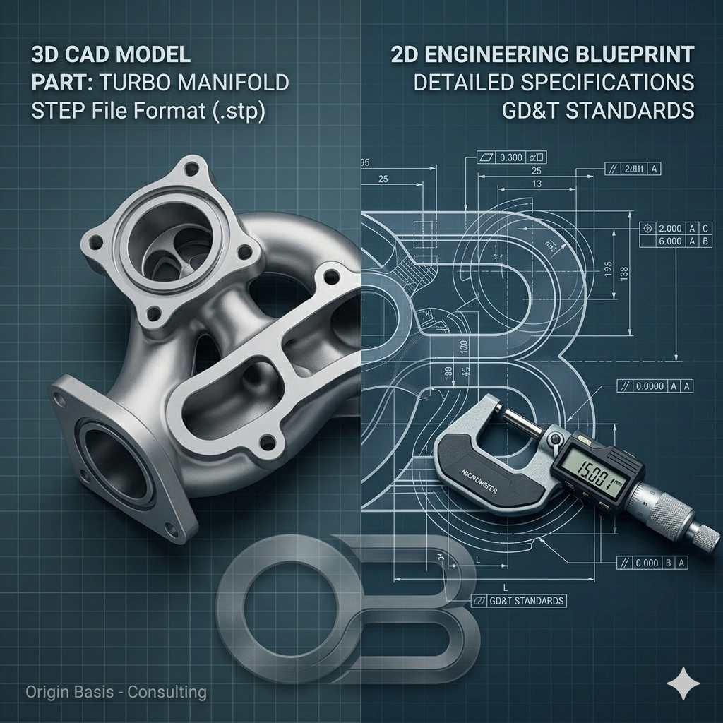
2. The Manufacturing Blueprint: 2D Technical Drawings
A common misconception is that a 3D CAD file is all a machinist needs. While a 3D model provides the shape, a 2D technical drawing (usually sent as a PDF) provides the intent. Your 3D model cannot communicate threads, internal tolerances, or surface finishes. For high-precision, mission-critical applications like aerospace and medical machining, a 2D engineering blueprint is mandatory.
Your 2D drawing should clearly highlight:
- Critical Dimensions: Pinpoint the areas where fit and function are vital.
- Thread and Hole Specifications: Define thread sizes, pitches, depths, and tapped hole requirements (e.g., M6x1.0 or 1/4-20 UNC).
- Geometric Dimensioning & Tolerancing (GD&T): Use standard GD&T symbols to define flatness, concentricity, parallelism, and true position for critical interfaces.
- Surface Finish Requirements: Specify the required surface roughness using Ra values (e.g., 1.6 µm or 32 µin) so the shop knows whether standard machining finishes are acceptable or if post-processing is necessary.
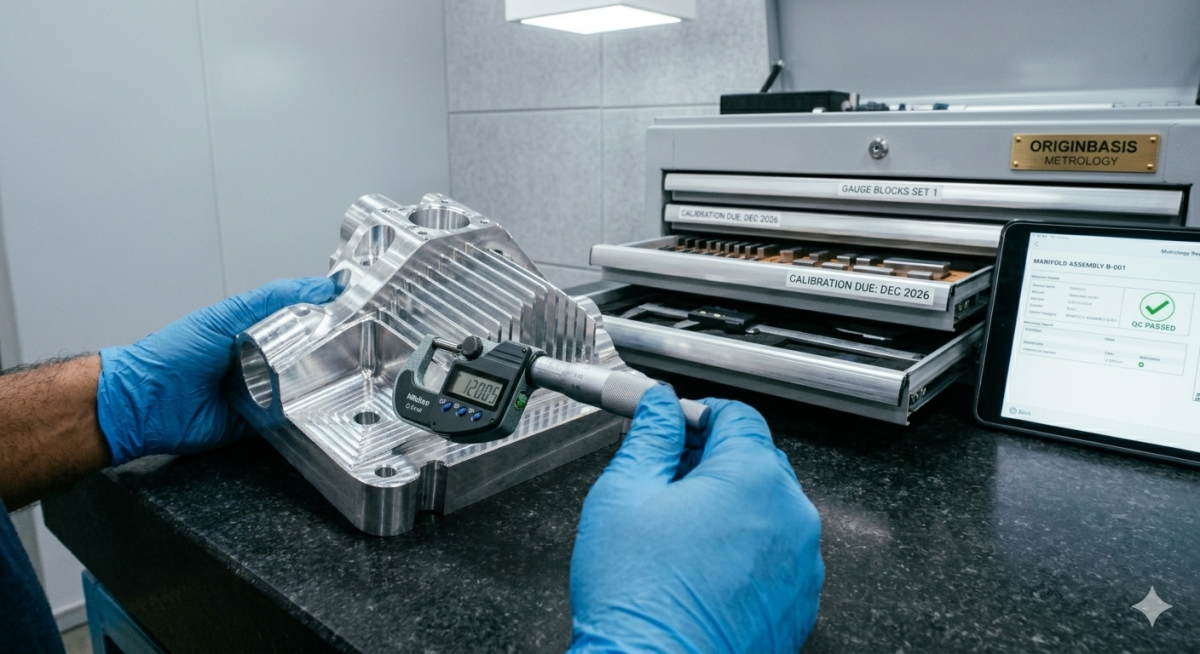
3. Defining Machining Tolerances: Standard vs. Tight
Tolerances dictate how much variance is acceptable from your nominal design dimensions. Clearly stating your tolerances protects your design’s functionality and keeps your production costs in check.
- Commercial/Standard Tolerances: If your drawing doesn't specify unique tolerances, most machine shops default to standard limits (typically ±0.125 mm or ±0.005 inches).
- High-Precision Tolerances: For advanced components, tolerances frequently dip down to microns (e.g., ±0.01 mm or ±0.0005 inches).
Pro Tip: Only apply tight tolerances to features that absolutely require them (like bearing seats or mating alignments). Over-specifying tight tolerances across non-critical dimensions drastically increases machining time, inspection protocols, and overall cost.
4. Don’t Forget the Administrative Metadata
Beyond the geometry, a machine shop needs clear operational context to build a reliable quote. Make sure your RFQ document explicitly lists:
- Exact Material Grades: Don't just say "Aluminum." Specify the exact grade and temper (e.g., Aluminum 6061-T6, Aluminum 7075-T6, Stainless Steel 316L, or Titanium Grade 5).
- Production Volume: Indicate your desired batch size. Are you looking for a single prototype, a bridge-production run of 50 units, or long-term contract manufacturing? Volume significantly affects material sourcing and tooling setups, which changes the per-part cost.
- Surface Treatments & Post-Processing: If your parts require anodizing (Type II or Type III hardcoat), passivation, chemical film, powder coating, or heat treatment, specify it upfront.
- Certifications & Compliance: If your parts are for regulated industries, state if you require standard material test reports (MTRs), Certificate of Conformance (CoC), First Article Inspection (FAI) reports, or compliance with specific quality frameworks like ISO 9001 or AS9100.
Streamline Your Next Project with Origin Basis
Providing a complete data package ensures your project moves smoothly from your desktop straight to the production floor without friction.
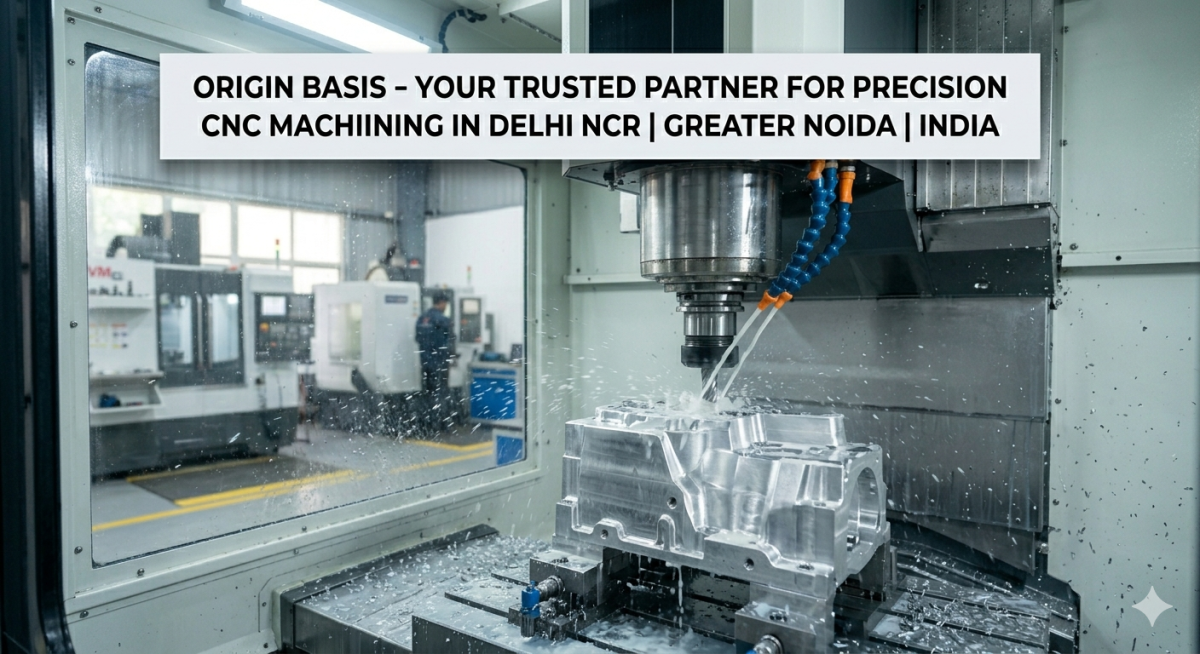
At Origin Basis, we specialize in precision CNC machining built to world-class quality standards. Whether you are launching a complex aerospace prototype or scaling up production for specialized medical-grade components, our engineering team is ready to analyze your RFQ package and deliver optimized manufacturing solutions.
Ready to start your next project? Gather your STEP files and 2D drawings, and reach out to the engineering team at originbasis.com today to request a comprehensive, accurate CNC machining quote.